Sunday, May 27, 2018

Film simulation with Olympus!

Any modern mirrorless or DSLR cameras do have color profile management which, with Fujifilm cameras, is called Film Simulation.

In this blog post, I would try simulating Fuji's Film Simulation with Olympus cameras!

Film Simulation under the hood

Fuji discloses in this article that Film Simulation is fundamentally an adjustment of Tonality and Saturation. By 'Tonality' they would mean Contrast.

Now with Olympus cameras, we can adjust Contrast and Saturation in five steps between -2 to +2 (in-camera or in-post using Olympus Viewer). (FYI, other manufacturers have more steps: eg. Sony has -3 to +3, Panasonic has -5 to +5.)

So it is assumed that Film Simulation may be attained by adjusting Contrast and Saturation in the following way.

Initially I have tried with these settings and have achieved mostly satisfying results but after close inspection of images from Fuji's true Film Simulation, I have found that contrast in ProNeg Hi is actually higher than Astia and comparable to Provia, so I decided to make contrast in ProNeg Hi zero(0) rather than -1.

So let's give it a try!

Nature (flower)

(May take a while until images are fully loaded. Can be enlarged full screen.)

You can see that, in this context, Provia or Velvia would make subject more attractive while Classic Chrome is obviously not suitable here.

Architecture (historical)


In this situation Classic Chrome may best tell the 'story', while Velvia does not work well here.

Portrait


Strong contrast is best avoided in this context and softer tone is much preferred. I like Astia or ProNeg Std version here.

Characteristics of each mode


The Default - Provia

General purpose 'Standard' mode that is suitable for most situations. However, for images to look pleasant, Contrast and Saturation may be a little pushed up than real.

Muted Sequence - Astia, ProNeg Hi, ProNeg Std

Since the "Standard" Provia is a little exaggerated, more realistic, natural (softer) modes are in order in some situations including portraits. When Contrast is somewhat detuned, it's called Astia, while in ProNeg Hi Saturation is attenuated instead. ProNeg Std is the 'softest' version where both Contrast and Saturation are reduced.

Artistic Modes - Classic Chrome and Velvia

These two modes with enhanced Contrast and/or Saturation opt for specific artistic situations and can be a very strong tool to convey particular photographic story.

Wednesday, November 30, 2016

Understanding White Balance on Color Wheel

RGB Color Wheel

Firstly, have a look at this color wheel. This is based on RGB Color Model. There is another color wheel called CMY Color Wheel, but they are basically the same, only somewhat rotated.

There is still another color wheel called RYB Color Wheel, which is somehow more popular on the web. And this color wheel is clearly different from the two mentioned above. In this wheel, Red, Blue and Yellow (instead of Green) are the primary colors. Do your own image searches to find out how different those color wheels are.

In this post, I only refer to RGB Color Wheel shown above because I believe that is the only one relevant to this topic. See how nicely additive (RGB) and subtractive (CMY) primary colors are arranged in a triangular, complementary manner!

White Balance

I'm sure you already know about color temperature with regard to white balance. So I skip discussion about it altogether here. It is a linear scale that has warmer (Amber) and cooler (Blue) sides on its ends. However, that's not the whole story. There is another axis called tint that is perpendicular to that temperature axis. It usually has greeny and purplish ends and often used to compensate greenish cast of fluorescent lights. So most advanced level cameras have both temperature and tint controls whereas entry level cameras may only have temperature control.

Let's see how color temperature and tint are mapped on the color wheel.
As you can see, Amber is not a primary (or even secondary) color and can be found halfway between Yellow and Red. The opposite of it is often called "Blue" in the discussion of color temperature, but it actually is not the same blue as the Blue of the RGB, because it is located halfway between Cyan and RGB Blue and so is somewhat whiter than RGB Blue.

Now let's look at tint. On this wheel, it has the Green of RGB on one end and the Magenta of CMY on the other. Yes, they are just primary or secondary colors.

You will use two controls (temperature and tint) on the white balance menu in your camera, but what it actually does is to change the hue (and saturation) in the color wheel.

Fixing Color Cast Effectively

I often find it rather difficult to correctly fix a particular color cast in my cameras. The reason is that there is no clue about which and how much of four colors (Amber-"Blue" and Green-Magenta) I should add or subtract.

Let's look at those four colors again.
Do you know how much of these strange colors you should add or subtract when you need to add some yellows on, or remove some redness from your image?

So now I'll try to remedy this situation.

First I rotated the color wheel 30 degrees counter-clockwise to make things little easier. Now temperature becomes vertical axis and tint is horizontal axis.
And I also gave better names for tertiary ("between") colors. Note that I renamed "Blue" of the color temperature as Azure.

If you wish to compensate a particular color cast, now what you should do is
  • to find a complementary color of that cast over the wheel above
  • then add that color with the two controls of temperature (A-B) and tint (G-M) on your camera menu
  • adjust the amount of fix considering how far you should shift using two controls.

Examples

I mainly use Olympus and Sony cameras. To me each of them has particular color cast under Auto White Balance setting.
  • Olympus XZ-1: AWB has reddish cast. To compensate this, I need to shift toward Cyan somewhat. So I would do, for example, A-2, G+1 (two steps toward Azure and one step toward Green).
  • Olympus E-PL2: AWB has yellow or somewhat chartreuse cast. The opposite of them are RGB Blue and violet. So, for example, I would do A-2, G-2 (two steps each toward Azure and Magenta).
  • Sony a5000: AWB sometimes looks too cool. This case is simple, I can fix by modifying only temperature. For example, I would do A+2, G0 (two steps toward Amber, leaving G-M at zero).

Notes

You may ask, exactly what RGB values I used to make the wheel? Here is the answer.

 primary (secondary) colors   tertiary colors
 Red  #FF0000  Amber  #FF7F00 
 Green  #00FF00  Rose  #FF007F
 Blue  #0000FF  Violet  #7F00FF
 Cyan  #00FFFF  Azure  #007FFF
 Magenta  #FF00FF  Spring Green   #00FF7F
 Yellow  #FFFF00  Chartreuse  #7FFF00

In some applications (eg. RAW developing software), however, the colors representing the temperature axis are not Amber and "Blue" (actually Azure) but rather Yellow and Blue (the true RGB Blue). In these cases, even though the colors representing the tint axis may be called "Green" and "Magenta", they are actually 30 degrees tilted version of them, Spring Green and Rose.


In other words, in most applications the four fundamental colors are Amber, "Blue" (actually Azure), Green and Magenta.


Whereas in others they are Yellow, (the true) Blue, "Green" (actually Spring Green) and "Magenta (or Red)" (actually Rose).

Friday, December 19, 2014

How to Key Your Amplifiers with TS-590(G) or TS-990

In Yahoo Groups forums I've seen so many posts asking about how to hook up TS-590(G) or TS-990 to an amplifier via the REMOTE connector to key it properly and how to configure in the menu setting for it.

I too was confused initially and have found Kenwood's explanation in Instruction Manuals (TS-590TS-590G, TS-990) and In-Depth Manuals (TS-590, TS-990) rather vague and inadequate. So here's my attempt to shed some light on this.


Two Ways to Key Amplifiers


You must first understand that there are TWO ways to key your amplifiers through the REMOTE connector and their relevant pin-outs are different.


Using Mechanical Relay

There is a mechanical relay inside the radio behind the REMOTE connector. Here's the actual part used in most Kenwood rigs. It's made by Panasonic (or NAIS, Aromat) and the datasheet is here.
DS1E-M-DC12V (Panasonic)
 pros
  • Higher ratings
    • As printed on the package above. Or to put it another way, the max ratings are
     60W or 125VA 
     DC 220V or AC 250V 
     3A 
    • This can be safely used, without a buffer, with older tube amplifiers.
  • Easier connection
    • You can hook up directly with a DIN-to-RCA cable that you can make up easily using a plain phono cable.
 cons 
  • Noisier
    • Produces clicks that can be annoying. (But consider that your amplifier relay may also create even greater noise.)
  • Concern about lifetime
    • According to the datasheet its mechanical endurance is more than 108. This is astronomical enough so we need not worry about its lifetime, but who knows about premature failure due to extremely harsh use, like making more than 3,000Qs in CQ WW contests? Or in DXpeditions?

Hooking it Up
To use this relay, hook up pin4(MKE) and pin2(COM) of the REMOTE connector directly with the relay control (RCA jack) of the amplifier.


MKE and COM are shorted while TX. They are really just a relay contact and isolated completely from other circuits, so the polarity between the two doesn't matter (interchangeable). Remember that COM is floating and has nothing to do with the circuit ground. (See schematics at the end of this article for details.)

Using Solid State Switches

Alternatively you can use solid state switches inside the keying circuit. They are comprised of several components but the main part is 2SB1188 bipolar transistor for 'Active High' and 2SK1824-A (or SSM3K15AMFV) MOSFET for 'Active Low' configurations. These are tiny little SMD parts.
2SB1188 (left), 2SK1824 (right)

 pros
  • Quieter
    • Yes, but you may still hear some clicks since there are other T/R relays inside the radio, not to mention keying relays in the amplifier.
  • Longer lifetime
    • Hopefully, infinite.
 cons 
  • VERY limited ratings
    • Usually for this type of solid state keying, the current rating is in around 100 to 200mA range with radios from other manufacturers (eg. Yaesu, ICOM). But unfortunately, Kenwood has designed this to have only 10mA as the recommended maximum.
    • So using a buffer is the safer approach.

Hooking it Up
With TS-590G and TS-990 you have two configurations to choose from, 'Active High' and 'Active Low', whilst TS-590 (non-G) only has 'Active High' configuration.

'Active High' configuration
With this configuration, pin7(RL) is pulled up to DC 12V while TX. RX status is not 'Low' or 'Ground' but 'undefined' (floating). To use this configuration, you probably need an inversion buffer between the exciter (radio) and the amplifier. There are many commercial solutions but here is my attempt using a digital transistor (a transistor with built-in bias resistors). (Tnx to JA7UDE, Oba-san for suggestions.)


Here is the part I used above and the datasheet is here. Since this is a 'single part' project, you can even house this inside the casing of a DIN plug.
It has 50V, 30mA (100mA max) output rating so can be used with most solid state amplifiers but may not be used with older tube amplifiers with higher keying voltage. You can choose a similar device that has large enough output (open collector) rating to match your amplifier's keying specification and ensure to limit the base current well below 10mA.

Here's another attempt using a photo-relay that has much larger tolerance.


Here is the part I used and the datasheet is here. In this case cramming all parts (including a resistor and a diode) into a DIN casing may be more difficult.
This particular device (Toshiba TLP222G) has 350V, 120mA output tolerance so this will safely key virtually ANY (including older tube) amplifiers. Again please ensure input current to be less than 10mA.

Added benefit is that now the radio and the amplifier are galvanically isolated over this line, so hopefully less vulnerable to RFI. (Though you may still have unisolated ALC line.)

'Active Low' configuration
With this configuration, pin7(RL) is pulled down to the (near) ground while TX. RX status is again not 'High' but 'undefined' (floating). So for this setting to work, the pin7 needs to be pulled up externally while RX (usually by a buffer or an amplifier).

Personally I've never been able to utilise this configuration. Kenwood recommends maximum resting voltage of 15V at RX and keying current less than 10mA while TX that seem too low for direct keying. Here are some of the keying specifications from amplifier manufacturers.

 IC-PW1   DC 5V, 20mA 
 JRL-2000F   DC 12V, 5mA 
 KPA500   DC 5V, 1mA 

It appears that JRL-2000F and KPA500 are within Kenwood's recommendation so they can be keyed safely with a direct cable (no buffer) below.


As to IC-PW1, I have actually measured keying current which turned out to be 8 to 10mA. This is less than what ICOM suggests and, narrowly though, within Kenwood's recommendation. When I tested, it works but there was a slight problem (see the table below). Also please remember that ICOM recommends the use of a buffer if the exciter's keying specification is less than 0.1A.

If you look at the datasheet of 2SK1824 (or SSM3K15AFMV), you'll see that the actual parts have 30V, 100mA maximum ratings. As the keying specification for most of the newer solid state and tube amplifiers fall within this limit, they may also be safely keyed with this cable. Here are measurements and test results with some of the modern amplifiers. (Tnx Rob NC0B and John K9EL)

 model 
 RX 
 TX 
 works? (comments) 
 resting 
 voltage 
 keying 
 voltage 
 keying 
 current 
 Alpha 89
 12.2V 
 1.17V 
 12.4mA 
 Yes. 
 Alpha 99 
 25.3V 
 0.65V 
 6.6mA 
 Yes, but close to the 30V spec of the 
 device.
 Alpha 9500
 8V 
 0.14V 
 2mA 
 Yes. 
 ACOM 1000 
 11.7V 
 1.02V 
 10.8mA 
 Yes.
 IC-PW1 
 4.30~ 
 4.37V 
 0.72~ 
 0.73V 
 8.0~ 
 8.2mA 
 Yes, it keys and amp works well, but 
 with some units 'TRANSMIT' LED 
 on PW1 won't light up, probably due 
 to not enough voltage drop over that 
 'yellow-green' LED. 
 THP HL-550 
 10.5V 
 2.7V 
 27mA 
 No. Too much voltage drop across the 
 internal 100 ohm resistor in series 
 with the FET drain. +2.7V not low 
 enough to key the amp. (See the 
 schematics and discussion below.) 

 pin7 = ReLay ??
  • Many times I wondered, why pin7 is labeled as RL? Because the ReLay is not there! My guess is that, Kenwood has meant "a terminal provided to control an amplifier's ReLay." Anyway this is another source of confusion. 


The Menu Settings


Along with the cable wiring, you have to choose the right option in the radio's Linear Amplifier Control Menu for the above configuration to work as intended.

 'Active High' and 'Active Low' only pertain to the logic mode of the solid state switches
and have nothing to do with the operation of the mechanical relay.

You probably have already understood this through the discussion so far. Though the relay may seem to play just like 'Active Low' (contacts shorted while TX), but you MUST NOT choose this option only for this reason. To activate the relay, you should instead choose the option with 'Relay Control'.

TS-590: Menu #53 (HF) and #54 (50MHz)


Non-G version of TS-590 has just three options and they all activate pin7(RL) in 'Active High' mode. It does NOT have 'Active Low' mode.

To activate the mechanical relay, choose either '2' or '3'. Clicks should be heard. The option '3' has slightly more delay time to be used with slower switching amplifiers (eg. older tubes).

If you wish to avoid noise and wearing of the relay, '1' is the only option to choose.

TS-590G: Menu #59 (HF) and #60 (50MHz)


TS-990: Advanced Menu #11 (HF) and #12 (50MHz)


TS-590G and TS-990 are effectively identical though options are unnumbered in the latter. (I have added numbers for comprehension in the table.) They have five options and the two newly added ones are 'Active Low' options, '4' and '5'.

Options '1', '2' and '3' are identical with non-G version of TS-590. To activate the mechanical relay, you should choose either '2' or '3'.

Options '3' and '5' will add a little more TX delay. The delay time for modes SSB, FM and AM has been lengthened (45ms) compared to TS-590 (25ms), whilst the delay time for CW and FSK stays the same (25ms).
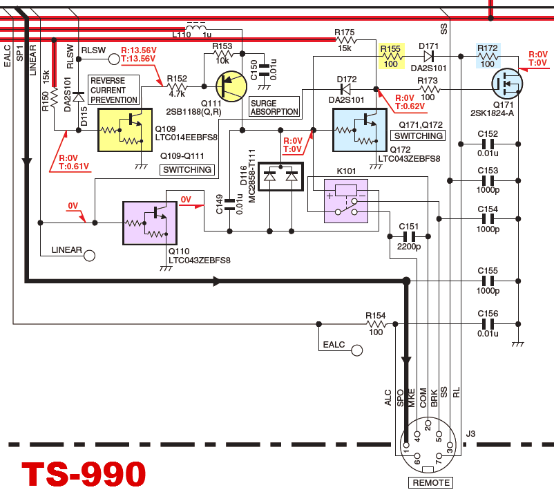

Under the Hood


For curious minds, here are the schematics of the keying circuit in each radio.


Let's take a look at TS-990 as an example. K101 is the mechanical relay and it's keyed by Q110 (digital transistor). For 'Active High' configuration, Q109 (digital transistor) switches on Q111 (2SB1188) that sources DC 12V for pin7(RL). For 'Active Low' configuration, Q172 (digital transistor) will key Q171 (MOSFET) that takes pin7(RL) to the ground. There are 100 ohms protective resistors inserted for both 'High' and 'Low' configurations (R155 and R172).

Due to this resistor, even in 'Active Low' mode, pin7(RL) cannot be fully pulled down to the true ground (0V) but will be left at slightly higher potential. For example, if 10mA is sourced while TX, pin7(RL) will be at 1V. This may go even higher as more current is sourced.


The circuit in TS-590G is almost identical with the TS-990's. The MOSFET (2SK1824) for 'Active Low' logic is now replaced by an SSM3K15AMFV, probably its successor.


As you can see, TS-590 (the original) has no 'Active Low' circuitry but otherwise the same with the other two.

Saturday, June 22, 2013

ViewProp: more charts

This is a continuation from the last post. Let's look at some more.

2013 JIDX CW

(2013/4/13) SFI=125, SSN=148, A=6, K=2

(2013/4/14) SFI=116, SSN=111, A=12, K=3

  • This 30-hour contest starts at 7z Saturday and ends at 13z Sunday. So there is a 6-hour overlap. That means we have two chances of high-band EU openings and low-band NA openings.
  • Being situated during one of the best times for DX (mid-spring), both high and low bands open pleasantly for a good amount of time.

2013 RDXC

(2013/3/16) SFI=126, SSN=90, A=10, K=2

(2013/3/17) SFI=125, SSN=126, A=72, K=5

  • This is more of an European contest so not as many NA spots seen.
  • From JA fifteen is already closed at the outset so we start rather slowly on 20.
  • Toward the end of the 2nd day it suffered from geomagnetic activity somewhat.
  • On the 2nd day, ten meters, for Europe and Russia, dried out completely by 8z, followed by 15 at around 10z. Two hours to go but I almost gave up the contest here since I became quite empty-handed, other than picking up weak NA stations on 40 and 80. (I was operating mobile entering low power CW.) I was quite surprised when I saw 15 came back to life (though a little bit) in the last minutes!

2013 ARRL DX CW

(2013/2/16) SFI=103, SSN=75, A=8, K=1

(2013/2/17) SFI=105, SSN=74, A=9, K=1


  • This one is a NA vs DX contest so let's focus only on NA side.
  • Sunspots are not quite but thanks to geomagnetic serenity, it made a good contest.
  • Apparently this still shows a typical WINTER condition with shorter high band and longer low band openings.
  • Ten meters' rate peak from JA is always at 2230z to 2330z.
  • Looks like we can sleep 'safely' between 17z and 20z. (Of course you can play with scatter on 10m etc.)

2012 WAE CW

(2012/8/11) SFI=119, SSN=98, A=4, K=0

(2012/8/12) SFI=112, SSN=76, A=7, K=2

  • This is an EU vs DX test so forget about NA part now.
  • This I remember was a tough contest. Although geomagnetic was within OK limit, the sun was stagnating. F-layer seemed not thick enough for 10m and there are also not enough darkness for 80m to travel through to Europe. So 10 and 80 were almost nothing.

2012 IARU HF

(2012/7/14) SFI=147, SSN=120, A=19, K=2

(2012/7/15) SFI=140, SSN=134, A=78, K=5

  • This one also suffered from geomagnetic storm especially on the 2nd day.
  • A typical summer condition but fifteen was not much impressive.
  • Ten had minimal openings and 80 was almost nothing.

Friday, June 21, 2013

ViewProp: Visualising openings from JA to Europe and North America

Kudos to Rick ZL2HAM, who has developed a truly fantastic tool called ViewProp, with which you can visualise RBN data in various ways (as well as traditional DX spots).

From a contester's perspective, I am very interested in the time course of the openings from JA to Europe and North America. Knowing and preparing for them are most crucial in contest strategy.

ViewProp can now load raw RBN spot data for a day of interest and do exactly what I need. I'll show you some examples here.

Click on images below to enlarge.
Each image has ten rows. The upper five are for EU (10-15-20-40-80 meters) and the lower five for NA.

2013 All Asian CW

(2013/6/15) SFI=110, SSN=101, A=3, K=1

(2013/6/16) SFI=115, SSN=104, A=3, K=1


  • This contest enjoyed typical summer openings through the night on high bands, often seen at cycle peaks.
  • Fifteen was open nearly 24 hours to Europe!
  • Although SSN hit 200 a few weeks ago, it unfortunately came down to around 100 now so openings on ten were marginal.
  • Twenty was also excellent especially for EU.
  • You can see very short openings on forty (and eighty) toward EU.
  • High band openings for NA in local mornings (around 0z) are surprisingly poor. This could be due to lack of participation from eastern NA being far flung from Asia.
.

2013 CQ WPX CW

(2013/5/25) SFI=121, SSN=107, A=37, K=4

(2013/5/26) SFI=120, SSN=92, A=18, K=4

  • This contest suffered greatly from a coincidental geomagnetic storm.
  • Compared to AA CW above, EU openings on 15 and 20 were significantly poor and 10 and 15 for NA were disastrous. (Openings in local Sunday morning were almost non-existent.)
OK, now let's see the big one in autumn.

2012 CQ WW CW

(2012/11/24) SFI=118, SSN=87, A=15, K=4

(2012/11/25) SFI=121, SSN=64, A=4, K=0

  • Compared to AA CW (in summer) above, this contest shows typical winter condition.
  • Ten and 15 openings are much shorter, while 40 and 80 much longer.
  • The initial running of day one for NA was a struggle, perhaps due to geomagnetic turbulence.
  • On the 2nd day local morning high band openings for NA were slightly improved.
I now realise CQ WW CW to be really a WINTER contest. Perhaps we need more focus on low bands (especially 40).
Now let's look at the year before.

2011 CQ WW CW

(2011/11/26) SFI=132, SSN=117, A=3, K=1

(2011/11/27) SFI=135, SSN=123, A=6, K=1

  • Geomagnetic activity quieter and solar indices higher than 2012 so 'shapes' are more normal.
  • Even so, 10m openings to EU were very short in duration.

Sunday, October 16, 2011

AP Sprint (Fall, CW) @Futtsu Point

I made a short trip to Futtsu Point, Chiba to kick ass in AP Sprint CW (20/15m). This is a mobile action.
Futtsu (pronounced like Footz) Point is located along the inner coastline of Boso Peninsula. It is some 50km away from my Tokyo home, but it's a comfy one hour driving via Aqua-Line Way.
The point is at the tip of shallow sandy land which has almost no elevation, and most importantly, open for nearly all directions. The best place for ham radio!
Apparently it's a place for surfing.
Straight to the west, you can even see Mt. Fuji (shady at the center of the picture).
Parked my Alfa 156 near the shore. The antenna is base-loaded whip by Diamond (MD-200). The element length is about 2m.
From another perspective. Radio sporting with Alfa Romeo. That's hot!
There is a huge, frame-built observatory overlooking Tokyo Bay at the tip of the Point.
At the controls. IC-706 control head is installed on its side to save the console's real estate. A paddle is located near the shift knob.
I use TR4W for most occasions.

And here is the result.

  AP Sprint 2011 Fall CW (20/15m)
  Call: JG1VGX/M, Location: Futtsu Point, Chiba
  Band  Qs  Pfx
  -------------
  15CW  17
  20CW  19
  -------------
  Total 36 x 21 = 756 points

This is not especially a spectacular result, but perhaps a good one for a mobile. Not many stations were around. I have enjoyed anyway. Thanks guys for taking up my weak signals.