I too was confused initially and have found Kenwood's explanation in Instruction Manuals (TS-590, TS-590G, TS-990) and In-Depth Manuals (TS-590, TS-990) rather vague and inadequate. So here's my attempt to shed some light on this.
Two Ways to Key Amplifiers
You must first understand that there are TWO ways to key your amplifiers through the REMOTE connector and their relevant pin-outs are different.

Using Mechanical Relay
There is a mechanical relay inside the radio behind the REMOTE connector. Here's the actual part used in most Kenwood rigs. It's made by Panasonic (or NAIS, Aromat) and the datasheet is here. |
| DS1E-M-DC12V (Panasonic) |
| pros |
|
|
| cons |
|
Hooking it Up
To use this relay, hook up pin4(MKE) and pin2(COM) of the REMOTE connector directly with the relay control (RCA jack) of the amplifier.

MKE and COM are shorted while TX. They are really just a relay contact and isolated completely from other circuits, so the polarity between the two doesn't matter (interchangeable). Remember that COM is floating and has nothing to do with the circuit ground. (See schematics at the end of this article for details.)
Using Solid State Switches
Alternatively you can use solid state switches inside the keying circuit. They are comprised of several components but the main part is 2SB1188 bipolar transistor for 'Active High' and 2SK1824-A (or SSM3K15AMFV) MOSFET for 'Active Low' configurations. These are tiny little SMD parts.

2SB1188 (left), 2SK1824 (right)
| pros |
|
| cons |
|
Hooking it Up
With TS-590G and TS-990 you have two configurations to choose from, 'Active High' and 'Active Low', whilst TS-590 (non-G) only has 'Active High' configuration.
'Active High' configuration
With this configuration, pin7(RL) is pulled up to DC 12V while TX. RX status is not 'Low' or 'Ground' but 'undefined' (floating). To use this configuration, you probably need an inversion buffer between the exciter (radio) and the amplifier. There are many commercial solutions but here is my attempt using a digital transistor (a transistor with built-in bias resistors). (Tnx to JA7UDE, Oba-san for suggestions.)
.png)
Here is the part I used above and the datasheet is here. Since this is a 'single part' project, you can even house this inside the casing of a DIN plug.
 It has 50V, 30mA (100mA max) output rating so can be used with most solid state amplifiers but may not be used with older tube amplifiers with higher keying voltage. You can choose a similar device that has large enough output (open collector) rating to match your amplifier's keying specification and ensure to limit the base current well below 10mA.
Here's another attempt using a photo-relay that has much larger tolerance.
.png)
Here is the part I used and the datasheet is here. In this case cramming all parts (including a resistor and a diode) into a DIN casing may be more difficult.
 This particular device (Toshiba TLP222G) has 350V, 120mA output tolerance so this will safely key virtually ANY (including older tube) amplifiers. Again please ensure input current to be less than 10mA.
Added benefit is that now the radio and the amplifier are galvanically isolated over this line, so hopefully less vulnerable to RFI. (Though you may still have unisolated ALC line.)
'Active Low' configuration
With this configuration, pin7(RL) is pulled down to the (near) ground while TX. RX status is again not 'High' but 'undefined' (floating). So for this setting to work, the pin7 needs to be pulled up externally while RX (usually by a buffer or an amplifier).
Personally I've never been able to utilise this configuration. Kenwood recommends maximum resting voltage of 15V at RX and keying current less than 10mA while TX that seem too low for direct keying. Here are some of the keying specifications from amplifier manufacturers.
It appears that JRL-2000F and KPA500 are within Kenwood's recommendation so they can be keyed safely with a direct cable (no buffer) below.
.png)
As to IC-PW1, I have actually measured keying current which turned out to be 8 to 10mA. This is less than what ICOM suggests and, narrowly though, within Kenwood's recommendation. When I tested, it works but there was a slight problem (see the table below). Also please remember that ICOM recommends the use of a buffer if the exciter's keying specification is less than 0.1A.
If you look at the datasheet of 2SK1824 (or SSM3K15AFMV), you'll see that the actual parts have 30V, 100mA maximum ratings. As the keying specification for most of the newer solid state and tube amplifiers fall within this limit, they may also be safely keyed with this cable. Here are measurements and test results with some of the modern amplifiers. (Tnx Rob NC0B and John K9EL)
With TS-590G and TS-990 you have two configurations to choose from, 'Active High' and 'Active Low', whilst TS-590 (non-G) only has 'Active High' configuration.
'Active High' configuration
With this configuration, pin7(RL) is pulled up to DC 12V while TX. RX status is not 'Low' or 'Ground' but 'undefined' (floating). To use this configuration, you probably need an inversion buffer between the exciter (radio) and the amplifier. There are many commercial solutions but here is my attempt using a digital transistor (a transistor with built-in bias resistors). (Tnx to JA7UDE, Oba-san for suggestions.)
Here is the part I used above and the datasheet is here. Since this is a 'single part' project, you can even house this inside the casing of a DIN plug.
Here's another attempt using a photo-relay that has much larger tolerance.
Here is the part I used and the datasheet is here. In this case cramming all parts (including a resistor and a diode) into a DIN casing may be more difficult.
Added benefit is that now the radio and the amplifier are galvanically isolated over this line, so hopefully less vulnerable to RFI. (Though you may still have unisolated ALC line.)
'Active Low' configuration
With this configuration, pin7(RL) is pulled down to the (near) ground while TX. RX status is again not 'High' but 'undefined' (floating). So for this setting to work, the pin7 needs to be pulled up externally while RX (usually by a buffer or an amplifier).
Personally I've never been able to utilise this configuration. Kenwood recommends maximum resting voltage of 15V at RX and keying current less than 10mA while TX that seem too low for direct keying. Here are some of the keying specifications from amplifier manufacturers.
| IC-PW1 | DC 5V, 20mA |
| JRL-2000F | DC 12V, 5mA |
| KPA500 | DC 5V, 1mA |
It appears that JRL-2000F and KPA500 are within Kenwood's recommendation so they can be keyed safely with a direct cable (no buffer) below.
As to IC-PW1, I have actually measured keying current which turned out to be 8 to 10mA. This is less than what ICOM suggests and, narrowly though, within Kenwood's recommendation. When I tested, it works but there was a slight problem (see the table below). Also please remember that ICOM recommends the use of a buffer if the exciter's keying specification is less than 0.1A.
If you look at the datasheet of 2SK1824 (or SSM3K15AFMV), you'll see that the actual parts have 30V, 100mA maximum ratings. As the keying specification for most of the newer solid state and tube amplifiers fall within this limit, they may also be safely keyed with this cable. Here are measurements and test results with some of the modern amplifiers. (Tnx Rob NC0B and John K9EL)
model
|
RX
|
TX
|
works? (comments)
|
|
resting
voltage
|
keying
voltage
|
keying
current
|
||
| Alpha 89 |
12.2V
|
1.17V
|
12.4mA
| Yes. |
| Alpha 99 |
25.3V
|
0.65V
|
6.6mA
|
Yes, but close to the 30V spec of the
device.
|
| Alpha 9500 |
8V
|
0.14V
|
2mA
|
Yes. |
| ACOM 1000 |
11.7V
|
1.02V
|
10.8mA
|
Yes. |
| IC-PW1 |
4.30~
4.37V
|
0.72~
0.73V
|
8.0~
8.2mA
|
Yes, it keys and amp works well, but
with some units 'TRANSMIT' LED
on PW1 won't light up, probably due
to not enough voltage drop over that
'yellow-green' LED.
|
| THP HL-550 |
10.5V
|
2.7V
|
27mA
|
No. Too much voltage drop across the
internal 100 ohm resistor in series
with the FET drain. +2.7V not low
enough to key the amp. (See the
schematics and discussion below.)
|
pin7 = ReLay ??
|
The Menu Settings
Along with the cable wiring, you have to choose the right option in the radio's Linear Amplifier Control Menu for the above configuration to work as intended.
'Active High' and 'Active Low' only pertain to the logic mode of the solid state switches,
and have nothing to do with the operation of the mechanical relay. |
You probably have already understood this through the discussion so far. Though the relay may seem to play just like 'Active Low' (contacts shorted while TX), but you MUST NOT choose this option only for this reason. To activate the relay, you should instead choose the option with 'Relay Control'.
TS-590: Menu #53 (HF) and #54 (50MHz)

Non-G version of TS-590 has just three options and they all activate pin7(RL) in 'Active High' mode. It does NOT have 'Active Low' mode.
To activate the mechanical relay, choose either '2' or '3'. Clicks should be heard. The option '3' has slightly more delay time to be used with slower switching amplifiers (eg. older tubes).
If you wish to avoid noise and wearing of the relay, '1' is the only option to choose.
TS-590G: Menu #59 (HF) and #60 (50MHz)

TS-990: Advanced Menu #11 (HF) and #12 (50MHz)

TS-590G and TS-990 are effectively identical though options are unnumbered in the latter. (I have added numbers for comprehension in the table.) They have five options and the two newly added ones are 'Active Low' options, '4' and '5'.
Options '1', '2' and '3' are identical with non-G version of TS-590. To activate the mechanical relay, you should choose either '2' or '3'.
Options '3' and '5' will add a little more TX delay. The delay time for modes SSB, FM and AM has been lengthened (45ms) compared to TS-590 (25ms), whilst the delay time for CW and FSK stays the same (25ms).
Options '1', '2' and '3' are identical with non-G version of TS-590. To activate the mechanical relay, you should choose either '2' or '3'.
Options '3' and '5' will add a little more TX delay. The delay time for modes SSB, FM and AM has been lengthened (45ms) compared to TS-590 (25ms), whilst the delay time for CW and FSK stays the same (25ms).
Under the Hood
For curious minds, here are the schematics of the keying circuit in each radio.
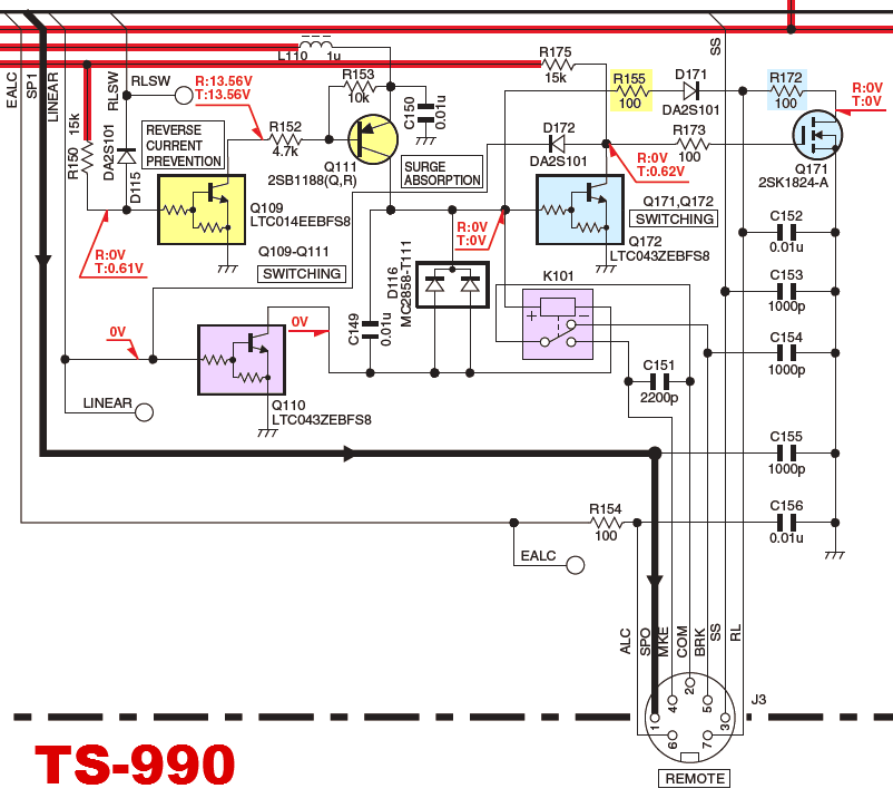
Let's take a look at TS-990 as an example. K101 is the mechanical relay and it's keyed by Q110 (digital transistor). For 'Active High' configuration, Q109 (digital transistor) switches on Q111 (2SB1188) that sources DC 12V for pin7(RL). For 'Active Low' configuration, Q172 (digital transistor) will key Q171 (MOSFET) that takes pin7(RL) to the ground. There are 100 ohms protective resistors inserted for both 'High' and 'Low' configurations (R155 and R172).
Due to this resistor, even in 'Active Low' mode, pin7(RL) cannot be fully pulled down to the true ground (0V) but will be left at slightly higher potential. For example, if 10mA is sourced while TX, pin7(RL) will be at 1V. This may go even higher as more current is sourced.

The circuit in TS-590G is almost identical with the TS-990's. The MOSFET (2SK1824) for 'Active Low' logic is now replaced by an SSM3K15AMFV, probably its successor.

As you can see, TS-590 (the original) has no 'Active Low' circuitry but otherwise the same with the other two.